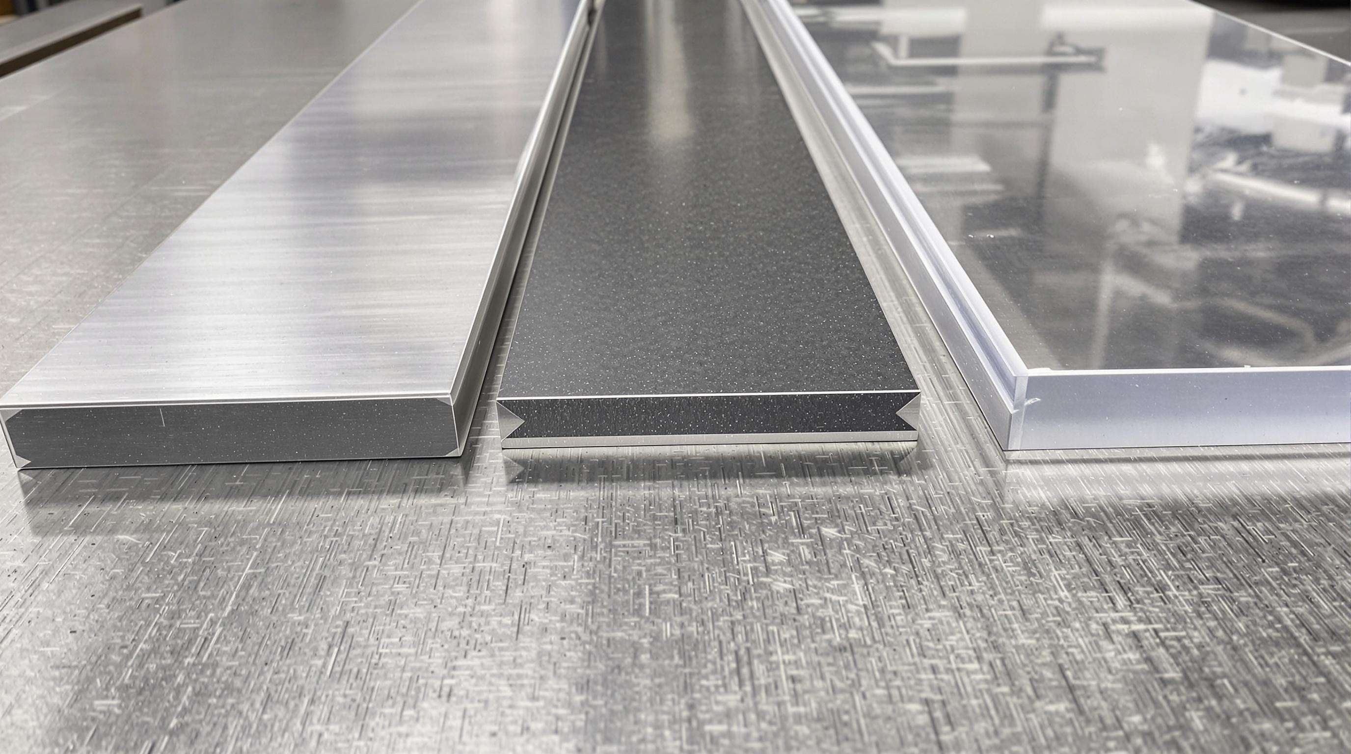
The term kerf width basically describes how much material gets cut away during machining processes, which affects both how efficiently materials are used and what size the finished parts end up being. When looking at precision cutting equipment, we generally see kerf widths varying quite a bit depending on the technology involved. Advanced laser systems can achieve incredibly narrow cuts around 0.1mm while waterjets usually leave behind wider gaps measuring about 1.0mm across. Research published recently shows that reducing kerf width actually cuts down on wasted material by approximately 18% when working with sheet metals according to Kechagias and colleagues in their 2023 study. For manufacturers focused on keeping production costs low without sacrificing quality, understanding and optimizing kerf dimensions becomes absolutely essential.
Modern machines achieve ±0.02mm kerf consistency through synchronized components:
Research from the Journal of Materials Mechatronics demonstrates how optimized machine designs improve kerf width consistency by 15–20% compared to conventional systems.
Material properties dictate ideal kerf specifications:
| Material | Recommended Kerf Width | Key Consideration |
|---|---|---|
| Stainless Steel | 0.15–0.25mm | Thermal conductivity management |
| Carbon Fiber | 0.3–0.5mm | Delamination prevention |
| Acrylic | 0.08–0.12mm | Melt-back control |
Recent findings from Der et al. (2023) reveal copper alloys require 22% wider kerfs than aluminum equivalents to account for thermal dissipation properties.
The narrower the kerf width, the more material gets saved during manufacturing processes. According to research published last year, cutting down kerf width by just 0.15mm can boost material usage efficiency anywhere from 8 to 12 percent when working with sheet metals. Today's advanced laser technology manages kerf widths around 0.1mm for steel alloys, which allows manufacturers to pack parts closer together on sheets, saving roughly seven dollars forty cents per square meter of raw material in most cases. Traditional thermal cutting techniques such as plasma torches tend to leave behind significantly more scrap compared to fiber lasers because they create much wider cuts. The difference is quite substantial actually, with plasma cutting leaving kerfs between 0.8mm and 1.6mm wide while fiber lasers maintain much tighter tolerances ranging from 0.1mm to 0.3mm.
Industry tests have shown just how much difference kerf optimization can make when working with aluminum. Take a recent case where a 2mm thick 6061-T6 sheet was processed with 0.2mm laser kerfs instead of the standard 0.4mm ones. The results? Material yield jumped from around 86.3% to an impressive 92.4%. For companies running at medium volumes, this small change adds up to about $18,600 saved each year. But there's a catch worth noting. When kerfs get too narrow, below 0.15mm actually, something interesting happens. The machines need to slow down significantly to maintain good edge quality, which ends up increasing cycle times by nearly 18%. So while thinner kerfs save money on materials, they also eat into production efficiency if taken too far.
| Material Type | 0.3mm Kerf Yield | 0.2mm Kerf Yield | Improvement | Cut Quality Rating* |
|---|---|---|---|---|
| Stainless Steel 304 | 87.1% | 93.6% | +6.5% | 9.2/10 |
| Aluminum 5052 | 85.9% | 91.7% | +5.8% | 8.8/10 |
| Polycarbonate | 79.4% | 88.3% | +8.9% | 7.5/10 |
*Based on surface roughness and edge perpendicularity metrics
Operators must optimize five key parameters to maximize efficiency without compromising cuts:
Aerospace manufacturers have successfully implemented parametric modeling approaches to balance these factors, achieving 94% material yield while meeting AS9100 quality standards. This strategy reduces trial runs by 40% compared to traditional setup methods.
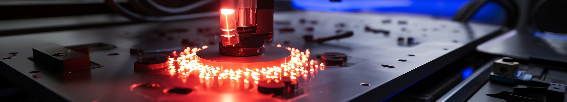
Today's precision cutting equipment makes use of both laser and waterjet technology, each with their own unique kerf properties. Laser cutters can produce really narrow cuts around 0.1 mm wide when working with thin metal sheets, though they need quite a bit more power when dealing with reflective surfaces. Waterjets take a different approach altogether. They typically create wider cuts measuring between 0.2 to 0.4 mm, but this method works well on all sorts of materials from hard stones to composite panels without causing much heat damage. The tradeoff is worth considering depending on what exactly needs to be cut and how important that extra precision might be for the final product.
| Parameter | Laser Cutting | Waterjet Cutting |
|---|---|---|
| Average Kerf Width | 0.1–0.3 mm | 0.2–0.4 mm |
| Material Flexibility | Metals, Plastics | Metals, Stone, Composites |
| Thermal Impact | High | None |
A 2023 Fabrication Institute study found waterjet systems reduce material waste by 18% compared to lasers when cutting mixed-material batches.
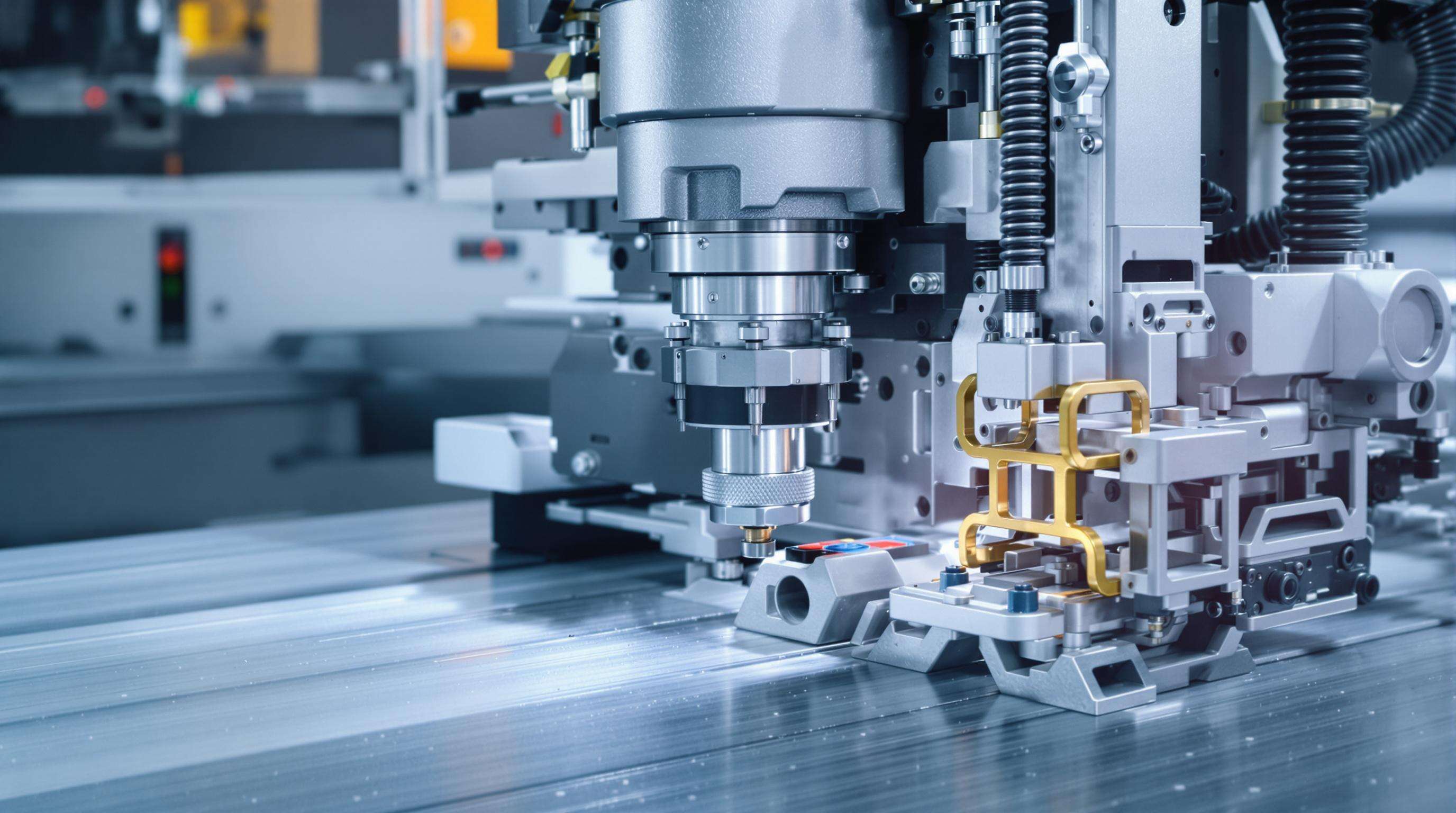
Computer Numerical Control (CNC) integration enables ±0.02 mm kerf tolerance through real-time adjustments. Modern systems utilize AI-driven path optimization algorithms that compensate for tool wear and material inconsistencies, achieving 98.7% cut consistency in aerospace aluminum components (Journal of Advanced Manufacturing, 2024).
Recent advances include:
These innovations collectively improve material yield by 22% in high-precision industries like microelectronics manufacturing.
Kerf width refers to the amount of material removed or cut away in a machining process, determining the efficiency of material use and size of the finished product.
Reducing kerf width saves material and improves efficiency. Narrower kerfs lead to more precise cuts and less wasted material, often reducing costs.
Precision is crucial for ensuring consistent product quality, minimizing material waste, and optimizing production costs.
Technologies such as laser cutting, waterjets, CNC integration, and advancements in nozzle and blade design help control kerf width and optimize material efficiency.


